Wednesday 11 November 2009


Horse Anatomy drawing project


To practice my drawing skills, a piece I will complete with emphasis on portraying motion. Using pencil and charcoal. It needs to be good as it will be a gift for someone. Im going to start laying down the foundations of the muscles, head etc using circles, then joining the circles to create a flowing line.


I have added some more shading, hair etc and general detail, maintaining the sketchy look I like


I have sketched out the muscles and added more definition as well as the maine, I like the expression on the face so far. The front right leg needs re-doing perhaps.


I have started to add some of the environment, mainly making the smokey dust the key feature as the horse is in motion. To create the dusty smokey effect I used a mix of pencil with gentle white charcoal. I have also added some soft shading to define the muscles around the front legs.


Wednesday 16 September 2009


Robot Arm Rigging Tutorial

For this tutorial i will be using Maya 8.5 it should work coherently with other versions of Maya aswell.

This tutorial is aimed at people who have a Robot type arm modeled already, as I will just be showing how to rig an arm that will allow the animator to animate the arm in an easy and clean way. As i want to achive purely robotic movements I will not be using IK or FK for this rig

1. Ensure you have deleted any history on your geometry.


2. The next step is to work out were you would like your joints placed in ur geometry. If you have modeled the actual joints into ur robot arm, this step is pretty easy. Press space bar and go into your side view. Make sure your in your Animation sub menu, and go to Skeleton > Joint Tool. Just roughly place your joint system for now.

3. Once placed go back to your perspective view, you might notice your joint system needs moving. To move your joint system select the top joint as it is the orgin (the first joint you create) and use 'w' key to move your joint system so the top joint now lives inside the shoulder geometry.
I would suggest showing the local rotation axes of your shoulder geometry, in my case i have a ball and socket type shape for my shoulder. To show the local rotation axes of a piece of geometry, select your geometry and go to Display > Transform Display > Local Rotation Axes. By doing this it shows you the centre of the geometry in my case it is helpfull as a I have a spherical shape. So now I can go to wireframe mode and select my top joint and by holding 'v' i can snap the top joint to the centre point of my geometry. (This step can be avoided, but it is helpfull if you want to be highly accurate). To stop showing the local rotation axes of an object just repeat Display > Transform Display > Local Rotation Axes.


4. The next step is to move the next joints into place, to select a joint lower down the chain you can tap the arrow keys on your keyboard. Remember you don't want to rotate any of your joints just translate them into place. At this point im going to add some joints to the palm and fingers of my robot hand. Repeat the steps used above Skeleton > Joint tool and place your 1st joint at the centre of the palm of your hand and carry on adding joints to the pivot points of the thumb. Once happy with your palm - thumb joint system press enter.
The joint you created at the palm is the root joint . So to now add a system of joints to the fingers you select the joint tool again and place your 1st joint right at the centre of the root joint. This will select the root joint and allow you to carry on adding joints to the fingers, Repeat this until all your fingers have a joint system.


5. We now have to connect are palm 'root' joint to the 'wrist' joint, so to do this select the palm 'root' joint followed by the wrist joint holding shift then go to Skeleton > Connect Joint - Option Box, and select Parent Joint. If you now select the wrist joint and move it about you will notice it now controls the palm and finger joints. Make sure you undo any movements you just made throught testing the wrist movement. Next step is to translate the joints to the right places so all the joints fit inside your hand geometry.


6. Next step is to label all of your joints, starting from the shoulder joint down to the finger tip joint. Use a similar labeling method for example, LtShoulder, LtElbow, LtWrist etc (Lt meaning left) when you get to the fingers use a system similar to, LtIndex_a, LtIndex_b, etc for the index finger. Just try and keep your labeling consistent.

7. Next step is to parent and group your geometry, Think about each piece of your geometry has been manufactured which parts are connected? For example the finger tip and the finger tip ball joint would be connected. Group the finger tip to the finger tip ball joint, (to group press ctrl +g) then the finger tip group needs to be grouped to the next finger tip section and the next finger tip ball joint. Label your groups as you go. repeat this process untill your finger has been properly grouped, you will know by selecting your finger tip geometry and by tapping up on your arrow keys you can hop between your differnt groups. Once your finger has been grouped , group it to the palm geometry. Repeat this for all fingers and the thumb. So when you press up on your arrow key you will eventually have the entire wrist selected. repeat this all the way up the arm, group the wrist to the fore arm etc etc.


Each image shows a different group in the hierarchy.

8. By doing this it helps to keep everything organized. Now select your top group, and shift select your root joint (the origin joint) which should be the shoulder joint and go to Skin > Bind Skin.
Now when you select a joint and move it your geometry will follow, remember to undo any movements you make while testing. Now we need to paint weight the geometry to the joints so we get no deformations. Select a piece of geometry i would suggest to start from the shoulder and work your way down. Once selected go to your animation shelf and select paint skin weights tool. (See picture below) once pressed go to the tools settings and select the relevant joint from the list, if you selected your shoulder geometry you will need to select the shoulder joint. scroll down in the options until you see a button called flood press this and you will notice your selected geometry go pure white. This means every thing that is white is now controlled by the joint you weighted it to. Repeat this process until all your geometry has been weighted to the correct joints. If you now have a play by rotating the joints you will notice you now get no deformation in your geometry :) Remember to undo any movements you make tho.

9. The next step is to create the control objects that the animator will use to animate the arm.
OK this section is kinda up to you creatively, you can either have a simple nurbs circle that you use to control a joint, or you could have a letter, anything! But the principle stays the same. I will use a simple nurbs circle. So create a nurbs circle by going to Create > Nurbs primitives > circle. The next step is pretty important so select ur shoulder joint and show its local rotation axes. Select your newly created nurbs circle and 'v' snap the cirlce to the local rotation axes of the shoulder joint. At this point scale your circle if you wish, then freeze transformations on your circle. So all the values = zero in your channel box. If you wish you can change the colour of your circle by going to its attributes by pressing ctrl +a, then select the nurbsCircle1 tab, scroll down to Display > Drawing Overrides > Enable Overrides > pick a colour. Name your circle.... LtShoulder_cc for example with the 'cc' standing for 'control curve'.

With your circle selected shift select your shoulder joint and go to Constrain >Parent constrain.
Your shoulder is now controlled by your LtShoulder_cc
Repeat the process for the elbow joint, but once your LtElbow_cc has been parented to your elbow joint, select your LtElbow_cc circle and parent it to your LtShoulder_cc by pressing 'p'. So when the shoulder is being moved by its control the elbow control will follow, repeat this for the LtWrist_cc but this time you would parent it to the LtElbow_cc. So the LtShoulder is the parent and the controls below it are the childs etc.

This wraps up the tutorial, I hope it has been helpful, This rig will allow the animator to move the arm in a robotic fashion by key framing the control curves. There are many ways you can develop this particular rig, you could use IK, FK you could add control curves to the fingers or add attributes to the wrist control so you can activate the fingers through attributes. You can be as creative as you like.


Saturday 5 September 2009

Tutorial: Modeling and Animating a Rocket with a Star trail


I will be using Maya 8.5 for this tutorial. The aims for this tutorial are to learn some basic modeling techniques as well as creating some basic animation. The tutorial will also teach you how to use geometry in conjunction with particle systems.

This tutorial im hoping will be a bit of fun, teaching you some basics aswell as giving you the freedom to design and create your own models/animations. Feel free to deviate from my exact designs if you feel comfortable. We will model and animate a rocket that emits a trail of stars from its exhaust.

1. First of we need to create a basic shape for the basis of our Rocket model. I have chosen to use a polygon cylinder with a subdivision axis of 10 and change the Subdivision Caps to 3. To alter the sub divisions of a polygon object, click polyCylinder1 in your channel box on the right hand side of your screen. (see picture 1) Once selected you have a few options were you can tweak your cylinder.

Picture 1

2. The next step is to edit our cylinder it make it resemble a rocket. select your cyclinder and hold the right mouse button over your object and select 'vertex'. By selecting each vertex you can tweak the shape of your ploygon mesh. (If you feel confident enough feel free to design and create your own rocket) I have sellected the top vertices and scaled them in slightly. To scale your vertices in Maya press 'r' on your keyboard once you have your vertices selected. You will notice your manipulator changes, the green box represents the Y, the red represents the X, the blue represents the Z and the yellow represents all of the above. Scaling using the yellow box will scale your vertices centrally. Use the yellow to scale your vertices slightly to give your rocket a more ...rockety shape. (see picture 2)

Picture 2

Still in vertex mode, select the middle vertex and raise it (see picture 3). Next make sure you are in polygon or modeling mode, depending on what Maya version you are using. (see picture 4) Go to Select > Select Edge Loop Tool. Use this tool to double click on a edge of topology on your model, it will allow you to select an entire loop so you can edit it. Use the Edge Loop tool to make the top of you rocket more cone shaped. (see picture 5)

Picture 3

Picture 4

Picture 5


3) Now your model is hopefully looking more like a rocket! The next step is to add a little detail to the middle of your rocket. The next tool you will need can be found under
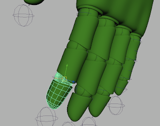
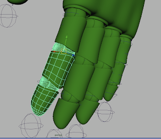
Edit Mesh > Insert Edge Loop Tool. This tool allows you to add a loop to your model, so once the tool has been selected add your loop to the middle of your rocket about 3/4 high. (see picture 6) With your loop still selected press 'r' and scale outwards slightly to give your rocket a more curved appearance. (see picture 7)

Picture 6

Picture 7


4) Were getting there just need to do some work on the bottom of the rocket. This is an area where you are free to be creative, there are a few possibilities you can go with for the bottom of your rocket. I am going to go for a more cartoony look. With the tools you have learnt so far you can decide what you would like your rocket to look like.


I have just added loops and scaled and moved them to get my rocket shape. Remember 'r' = Scale, 'w' = move. I am going to add some more detail to my model, using the extrude tool.
Edit Mesh > Extrude. Move your camera to the bottom of your model and select the inner rings of faces (see picture 8) To select the faces hold the right mouse bottom over your model and select faces. With the faces selected press 'r' and scale your faces outward so you live a thinner edge. (see picture 9) With your faces still selected go to Edit Mesh > Extrude, you will notice your manipulator has changed so press 'w' and move the newly extruded faces upward in the Y you can also scale your faces in. This added detail gives your rocket an exhaust. Ok you now have a pretty basic rocket shape made, feel free to be creative and to add detail etc.

Picture 8

Picture 9


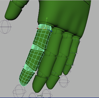
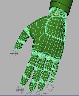
5) The next step is to make sure your model will smooth properly. We can do a test to show how important it is to make sure your model maintaines its shape when smoothed. So with your object selected goto Mesh >Smooth. You will notice your model has lost some of its shape, and it looks more organic. We dont particualrly want this effect so go back by pressing Undo. We need to add more loops to define the polygon mesh. Where you have a defined piece of geomnetry add an edge loop (see picture 10) In the picture you can see where i have highlighted the loops that i have added. This will keep the polygon mesh more crisp and defined when smoothed. Once you have added more definition hit smooth and see the effect you have now achieved. To see what i am now getting see picture 11.

Picture 10

Picture 11

6) The basic modeling is now complete for the rocket, you can colour it by creating shaders using the Hypershade. Window>Rendering Editors>Hypershade. You could try using a blinn if you would like a more shiny reflective look for your rocket.


7) The next step is to start animating our rocket. I will be attaching the rocket to a curve, to do this go to Create>EP Curve Tool. Press space bar and go to your side view, you can start drawing out your curve. Once you have drawn your curve in your side view go back to your perspective view and hold the right mouse button over your curve and select 'control vertex'. By selecting each vertex you can tweak your curve to make it more three dimensional, try and be creative by making your curve very curvy. (see picture 12)

Picture 12

8) Next make sure you are in the Animation menu instead of polygon or modeling. Select your rocket then shift select your curve then go to Animate >Motion paths> Attach to motion path - option box. Inside the option box set the time range to Time Slider, Tho following settings may differ for each person but what works for me is setting the Front Axis to Y, Up axis to Z. Then hit apply, your model should be facing upwards going along the curve like in picture 13. If you do hit play. Your rocket should now follow your curve :) to speed up or slow the pace of the rocket you can change how many frames the cycle lasts. By double clicking the green number at the tip of your curve you can adjust the number of frames the animation lasts, I have settled with 70.

Picture 13


9) Now for the exciting bit, if you havent already rewind the playback so its back at frame 1. Change the menu from Animation to Dynamics so you can access the particle menus. Goto Particles > Create Emitter. Move the emitter to inside the rockets exhaust (see picture 14) once you are happy with its placement select the emitter then shift select the rocket and press 'p'. This parents the emitter to the rocket, so were ever the rocket goes the emitter will follow.
If you press play you will notice the particles following the rocket. Remember to press rewind when finished testing, so you back at frame one.

Picture 14


10) The next step is model an object that will take the role of the particles, in this case it will be a star but you can always choose something else if you would like to have you rocket emit something different. To model the star we will start by creating a polygon cylinder with a Subdivision Axis of 5. By using insert edge loop tool you can add a line to each side, see picture 15.

Picture 15


Next select the vertices of the lines you have just added and scale them in, using 'r' and you will get a similar effect seen in picture 16. As you can see you have made a star! Using the Hypershade you can edit the colour of your star, could try using a blinn.

Picture 16

The next step is to move the star closer to your rocket and to scale it down to a size that would fit well if the star was emitted from the exhaust, but not to big so it looks odd but also not to small that you cant make out that it is a star. (Note: Once the star has been added to the particles, if you decide to scale the star, do this by scaling the original star you created. Ensure that you are still in the Dynamics menu, select your star then shift select your particles from the outliner, to view your outliner goto Window>Outliner. Ok so with your star and you particles selected goto Particles > Instancer (Replacement) - option box.

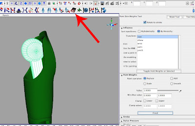
Within the Particle Instancer Option box, name your Particle Instancer name something relevant like 'star'. Scroll down make sure your Particle object to instance is set to the right particle, it should be 'particleShape1 then hit create. Play your animation and will notice that your rocket now emits stars! :) However if you play your animation to for example frame 40 and you can see that the stars that have been emited are not central to the rockets exhaust, there a little off. So to solve this select the newly added 'star1' in your Outliner, the icon should resemble 3 droplets. By pressing 'w' move the emitted stars so they fit better inside the exhaust. Once you are happy with the placemnt of the selcted emitted stars, rewind your animation to frame one. Now we can edit the attributes of teh particles, firstly select the emitter by double clciking it or pressing ctrl +a, scroll down to Basic Emission Speed Attributes and raise the speed to around 3.5. You can always tweak to your taste. You can also tweak the Particle Rate under Basic Emitter Attributes the higher the rate the more stars that will be emitted i have settled at 60. (see picture 17)

Picture 17


To add a glow to your stars, select your particles, in your attribute editor select particleShape1 and scroll down to Render Attributes and change Particle Render Type to Clouds. To edit the size of the clouds press Current Render Type just below, and edit the radius.
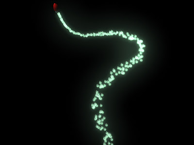
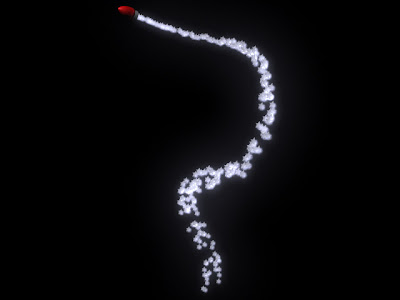
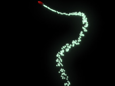
To edit the colour select particleCloud1 in your Hypershade, and go to its attributes and tweak the Colour, Transparency and the Incandescence. I like to keep a low Transparency so the stars appear as if they are glowing. To increase the glow you can also tweak the Glow Intensity. I have used a glow intensity of 0.153. Use Mental Ray when you render, to render an animation go to the render globals and change the extension to name.#.ext and change the image format to Targa [tga] type in the number of frames you have, I went with 70. You also have the choice of changing the image size i left mine at 640x480. Once you are ready make sure your in the rendering menu and select Render> Batch Render. I have posted some still renders below, also remember to make your animations even more exciting you can key the colours of the star particles as well as the clouds. By holding the right mouse button over the word colour in the attribute editor, you can select 'set key'. So in theory your star trail could change from green to red etc like a rainbow as the rocket flys through space!


Tutorial: Rendering Wireframe in Maya


Rendering Wireframes in Autodesk Maya

Through this tutorial I will be using Maya 8.5 , I have used a simple polygon cube as an example

1. The first step is to open the hypershade window - Window > Rendering Editors > Hypershade

2. The second step is to create a Background Shader using the Hypershade. (see picture 1)

Picture 1
3. Once the shader has been created select your object you wish to apply the shader to, with the object still selected go to the Hypershade window and hold down the right mouse button over the newly created shader and select 'Assign Material to Selection'.

4. The next step is to double click the shader to get to its Attributes or press ctrl + A. Change the Specular colour to black, the Reflectivity to 0, the Reflection Limit to 0 and the Shadow Mask needs to be 1. The Matte Opacity needs to be changed to - Solid Matte. (see picture 2)

Picture 2

5. Click the Output Connections button (see picture 3) Then click the Contours tab to expand the Contours options. Click the box to Enable Contour Rendering, here you have a few options to tweak your Wireframe render. You have the ability to change the colour and width of the wireframe. (see picture 4)

Picture 3

Picture 4


6. The next step is to edit the options in the Render Globals. See picture 5 to find the render global button. Once inside the Render Global settings window make sure you have mental ray as your renderer, scroll down to the Contours tab and expand it. Ensure the Enable Contour Rendering box is ticked. You can increase the Over-Sample to 3 to increase the quality. Also tick the box named Around all poly faces, (See picture 6). Once all of these steps have been achieved take a render of your object.

Picture 5

Picture 6


Wireframe Render

Friday 31 July 2009


Technorati code:86ueqispmg


Blade runner 3d model project


Project

To model a vehicle out of the film Blade Runner, my aim is to try and keep this thread up and running posting my progress as i work through the project. I will model the vehicle in Autodesk Maya, my aim is to replicate the original through researching the blueprints/schematics as well as observing as many images i can find on the internet to assist me in adding as much detail as possible. The final result will be a detailed polygon model of the original, textured and rendered to resemble as closely the vehicle from the film. If possible a short animation of the vehicle in motion as well.


sketching out the basic body mesh, concentrating on the curve of the cockpit. Laying down the topology that will help aid me later on when developing different areas. working on one side only as once complete, the mesh will be mirrored.

Sat 01 August

Continuing the main body area, concentrating on the cockpit area. Added the basic wing door shape. Going to continue sketching out the main areas trying to keep the poly count as low as possible.

Sun 02 August


Starting to model the side wing area, as well as sketching out the rear of the vehicle and top fin. My aim is to flesh out each major area of the vehicle before more detail can be added.


Mon 03 August

Continuing the rear of the vehicle, working on the placement of some details such as the lower chassis area. i decided to cut out the door as well as add a grill section to the front of the vehicle. I have started modeling the basic shape of the wheel area found towards the front of the vehicle. At this stage i'm finding i have to tweak the body slightly in different areas as i observe different reference images. I'm finding that some reference images vary slightly so i'm picking and choosing which images to go with when modeling some areas.


Tue 04 Aug

For a few days i was mulling over whether the front of the cockpit had a slight dip/slope to it, were the front portion begins. I was finding it hard to tell from still reference images, so i re- watched Blade Runner paying specific attention to the scenes containing the 'spinner' vehicle. I found that there was in fact a slight dip so i have now added that to the latest version of my model. I have been mainly focusing on the details of certain areas making sure there correct in comparison with the original Film model. I have also added more to the front wheel container areas, adding the caps and the spherical object to the side of it. In the film the side parts shielding the wheel actually rotate from vertical to horizontal. So i have been making sure if i decide later to rig my model for this exact function it will actual work. Each main area has been constructed to a basic mesh, my job now is to add the necessary detail.


Wed 05 Aug

Continuing working through the details, edited the front section of the vehicle and incorporated the lighting component. This area was tricky to model due to lack of reference images, i eventually found an image from the studio model so i worked from that mostly. I have also added small details to the wheel section. I have made small tweaks to the vehicle has i came across a selection of photos that showed the original studio model, so i have edited the mesh in comparison with the studio model photos, as i would like my model to resemble the original as closely as possible.


Thurs 06 Aug

Today i have been spending a lot of time comparing reference images as the area i planned to work on differed in a large way from image to image. The section i worked on was near the frame of the door, i have decided to work from the studio model reference as best as i can. I have also added small detail to the wheel section, this was tricky as the area i needed to work on, just behind the side wheel container. I couldn't find any detailed reference images at all so i had to use my judgement.


:Edit

I have continued to work on the oval section near the door frame. Im gradually getting it done to a point where i am happy with it. It still needs some work as it is a complicated piece of topology to create but my progress can be seen below. I have also added a smoothed version to show the effect i am generating which is pleasingly similar to the reference i am following.


Sat 08 Aug

I have been spending a lot of time recently working on the under-side of the 'spinner'. I managed to find some excellent material to reference from, It is still far from completion but the image below should give an idea of how its looking.

Sun 09 Aug

I have been continuing the work on the under side of the vehicle. All the basic shapes have now been modeled and are in place. A few more details need to be ironed out around the rear wheel area. I have also changed the material of the mesh just to keep the model fresh as i work on it. As the screenshots show the model is coming together.


Wed 12 Aug

I have recently been working on small details here and there as well as getting the model prepped before it is smoothed. This process takes some time because as i add more topology to define certain section it effects other sections in tandem. So i am working on getting the balance right at the moment. I have been working on the wheel section so far which can be seen in the picture below.


:Edit
Continuing to work on getting the mesh defined so it can be smoothed. Trying to keep a balance between definition and poly count. As a model is smoothed the mesh can get denser and denser as more definition via the polygons are added. The more dense a mesh is, the longer the render times. By keeping the poly count in mind as you model you can keep an eye on how long your scene will take to render. I'm working on defining the mesh of the main body of the vehicle at the moment. It still needs a lot of work but you can see how the under side of the body is shaping up from the picture below.


Sat 15 Aug

Its been a few days since i have worked on the model. I'm still defining the mesh so it can be smoothed. Focusing on making sure the topology is neat and correct.


Sun 16 Aug

Adding detail, The vehicle has a few grooves along the outer casing so i have been adding them as well as tidying up the topology. The vehicle is mostly un-organic in shape where it has straight sharp corners, lines and square shapes, but the top of the vehicle as well as a few sections on the bottom are more organic as it resembles a continuos curve. As the vehicle if made in real life would be manufactured using machines, to get this crisp and clean look the topology has to be neat and organized.


:Edit

Smoothed Door


Sat Aug 22

I have added some more detail to the door section. I have also been working on the rear section and decided the best method to define the rear is to brake the model up into each section or each 'panel'. I noticed through observing my reference images the rear of the 'spinner' is constructed in a similar way to a car. Each section is a separate panel that has been placed next to each other to form the rear. This can be seen in the following reference image,


Tues 25th Aug

I have been correcting some of the geometry at the rear of the vehicle, splitting up different sections into panels etc. Making sure the curve of the vehicle is consistent throughout each panel. Created the lamps that sit inside the rear light holder. I am beginning to work on the curved prong like object that sits on the left side of the vehicle, as well as making sure the underside of the vehicle is aligned with the rear and side sections of the vehicle. as well as filling out the empty space that lives inside the rear. Possible mechanical looking objects would suffice just to fill the empty gap

:Edit: I have done some more work to the side panel, which can be seen below


Wed 26th Aug

I have modeled the inner section of the door's frame as i am planning to model the interior. I have added detail to the two vents on the side of the spinner, by adding grills. I have also modeled the wheel that sits under the wing. I am mainly focusing on making sure each of the panels piece together like a jigsaw.


Edit:

I have separated and tweaked the separate panels (see below). Thickness has been added to each panel to give it more depth, as well as allow shadow to fill the gaps between each panel when rendered. From observing references I can see how the original vehicle was put together, and replicate the same method when I model. So I can replicate as much detail as possible.


Sat 19 Sept

Its been a while since iv worked on this project, So im going to see if i can progress tonight, I believe that the outer geometry is pretty much complete so i have started to mirror the geometry that is complete. Mainly the rear and bottom geometry.


Mon 21st September

I have been grouping my geometry and smoothing it, so I can produce some clay render tests.
I have added some renders below. I am pretty happy with the smoothed version of the model so far. A few tweaks will need to be made along with the modeling of the roof lights as well as the interior.


Testing some coloured shaders

Tues 22nd Sept

I have started working on creating the interior, its very rough at this stage but I have sketched out the shape for the dashboard and the middle control panel. I am struggling finding some decent reference images for the interior, so some of it may have to be guess work. I am enjoying it so far tho, the lack of reference allows for a bit of creative license.


Wed 23rd Sept

Continuing working on the interior. Adding detail to the dashboard section, I am finding my best references are coming from pausing the dvd and modeling from that. I feel its going quite well, the key to getting the interior to look right is to add plenty of detail to certain areas. Especially the control panels.


24 Thurs Sept

I have been working on the chair, adding small details.


Mon 28th Sept

continuing the detail on the chair, adding the head rest, duplicating geometry and placing it correctly inside the vehicles cockpit.


Tues 29th Sept

I have done a quick render test of the interior in its low poly form.


Sat 3rd oct

interior continued


Sun 04 Oct

I have built the binocular type object that almost floats within the cockpit. Some render tests can be seen below. Its still rough in terms of shaders being chosen etc, but the basic geometry is in place


Quick Update

I have added some more buttons etc to the control panel and added a pinkish tint to the environments sky to give the vehicle some standing and feeling of place.

Fri 9th Oct

I have been working on rendering and shading mostly in the past few days, playing around with neons and glow attributes. Any way I have added two renders below one of a night time scene possibly from street level and a brighter render that has a pinkish sky. (You may notice I have also modeled various buttons to the control panel, just to add detail)


Sun 11th Oct,

Continued work on the control panels that are placed around the vehicle. Testing shaders and different materials. Mainly adding more detail to areas that need it, the side door, the back plate behind the chairs etc.


A Finished Interior render, I have added more detail to the control panels, chairs' etc. I have also added some environment lighting through the use of neon. I am pretty pleased with the overall render especially with the lighting. I would still like to add some more detail to the different panels etc. For this particular render I feel I have achieved what I set out to do, in replicating the blade runner feel.